
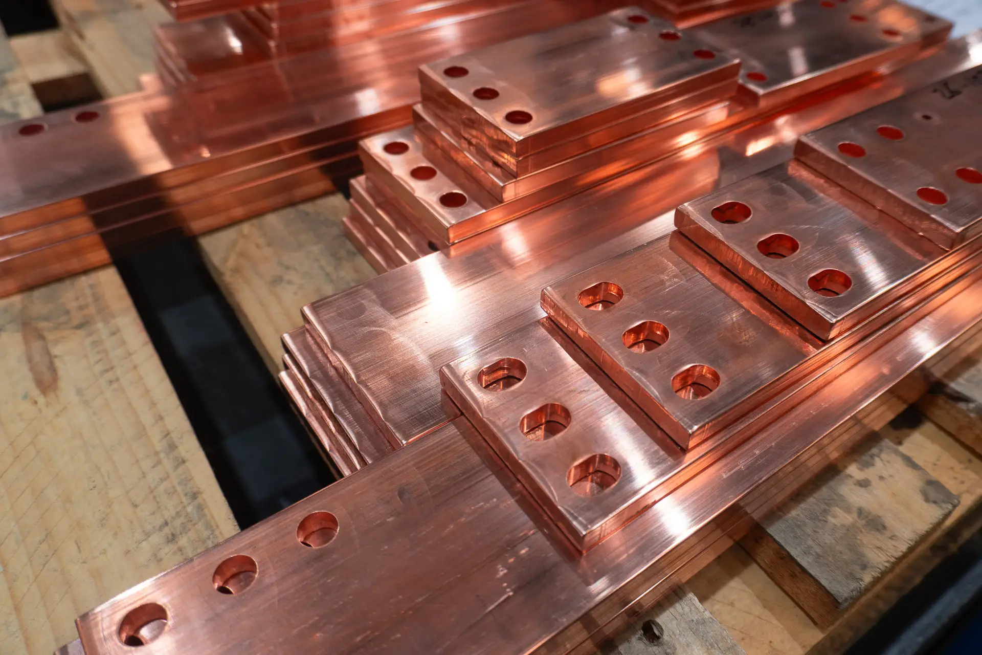
Correct copper busbar sizing depends on more than the current the conductor must carry. Engineers also need to consider permitted temperature rise, ambient conditions, the enclosure, short-circuit current, conductor geometry, joints, spacing and the requirements of the complete electrical assembly.
There is no universal busbar size for a given current. Two bars with the same cross-sectional area can carry different currents depending on their shape, how they are mounted and what surrounds them. The responsible engineer or system designer should determine the cross-sectional area and geometry from the electrical load, the operating conditions and the applicable standards.
ILF Products manufactures copper busbars to customer drawings and specifications from its Midlands facility, supported by copper stockholding, CNC machining, cutting, bending, punching and finishing.
Why Does Correct Copper Busbar Sizing Matter?
A busbar distributes electrical current between components within switchgear, controlgear, panel boards and other power distribution equipment.
An undersized conductor can contribute to excessive temperature rise, unwanted voltage drop or damage under fault conditions. Simply adding more copper is not always the answer, though. Larger bars add weight and material cost, take up enclosure space and can be harder to bend, punch and connect.
The right size is therefore a balance between electrical performance, the space available and the practicalities of manufacture.
How Do Engineers Approach Copper Busbar Sizing?
The exact method depends on the equipment and the standards it must meet, but a typical sizing process follows these steps:
- Define the load: continuous and maximum current, load profile and duty cycle.
- Set the limits: permitted temperature rise, ambient temperature and acceptable voltage drop.
- Estimate a starting cross-section from published rating data or the equipment manufacturer’s design rules.
- Choose the geometry: width, thickness, number of bars per phase, spacing and orientation.
- Check short-circuit withstand, including heating of the conductor and mechanical forces on the supports.
- Detail the joints: contact area, hole positions, fasteners and surface finish.
- Verify the design within the complete assembly, for example by test, by comparison with a tested reference design or, within defined limits, by calculation.
- Issue a controlled drawing for manufacture.
The sections below explain why each of these factors affects the final busbar dimensions.
Is There a Rule of Thumb for Copper Busbar Size?
Many quick estimates divide the design current by an assumed current density, in amps per square millimetre (A/mm²), to give a starting cross-sectional area. The current density figures quoted in published guides vary considerably, because each one assumes a different temperature rise, ambient temperature, enclosure and bar arrangement.
A current density figure can help with an early estimate. It cannot account for all the conditions found in a real electrical assembly. A single bar in free air, the same bar in a sealed enclosure and several bars per phase stacked closely together will all reach different temperatures at the same current.
Published rating tables, such as those in the Copper Development Association’s Publication 22, Copper for Busbars, state the conditions behind each rating. Check that those conditions match the actual installation before relying on any figure.
What Determines the Required Copper Busbar Size?
Continuous Current and Duty Cycle
Expected operating current is one of the starting points for copper busbar sizing, but it should not be assessed in isolation.
Engineers may need to establish:
- continuous and maximum operating current
- load profile and duty cycle
- acceptable voltage drop
- permitted operating temperature
- conductor arrangement
- installation environment
Copper combines high electrical conductivity with good thermal conductivity, which is why it is so widely used for high-current conductors. Even so, the load profile matters. Copper takes time to warm up, so short, intermittent peaks may not heat a bar as much as a steady load of the same value. That is why duty cycle can change the size required.
Temperature Rise and Cooling Conditions
Electrical resistance generates heat as current passes through the conductor.
How well a copper busbar sheds that heat depends on its surface area, orientation, ventilation and surrounding equipment. Surface finish plays a part too, because a dull or painted surface radiates heat more effectively than bright bare copper. A conductor operating freely in air may behave very differently once it is installed in enclosed switchgear.
The permitted temperature rise is usually set by the equipment standard, the insulation materials in contact with the bar and the devices connected to it. For more on managing heat in practice, see our guide to improving busbar heat dissipation.
Short-Circuit Current and Fault Duration
During a short circuit, a busbar may carry many times its normal current until the protective device clears the fault.
The fault current heats the conductor rapidly, and it also creates electromagnetic forces between neighbouring bars. Those forces rise with the square of the current and fall as the spacing between bars increases, so support positions and phase spacing matter as much as cross-section.
Low-voltage assemblies are commonly given a rated short-time withstand current for a stated duration, often one second. The prospective short-circuit current, protection characteristics, conductor spacing and support arrangement should all form part of the engineer’s assessment.
How Do Busbar Dimensions Affect Electrical Performance?
Width and thickness influence more than the total cross-sectional area.
Take two bars with the same 1,000 mm² cross-section. A 100 × 10 mm bar has a perimeter of 220 mm, while a 50 × 20 mm bar has a perimeter of only 140 mm. The wider, thinner bar has far more surface area to dissipate heat, so it will normally run cooler at the same current.
Geometry becomes more important still in AC systems because of skin effect and proximity effect. At 50 Hz, most of the current in copper flows within roughly 9 mm of the surface, so very thick bars use their copper less efficiently. Closely spaced bars also distort each other’s current distribution, which raises the effective resistance.
Using Several Bars per Phase
For higher currents, designers often use two or more bars per phase with a gap between them rather than one very thick bar. The gap lets air circulate between the bars, and each thinner bar is less affected by skin effect.
However, doubling the number of bars does not double the rating. The inner bars of a stack cannot dissipate heat as freely as the outer ones, and proximity effect increases the losses. Published ratings for multiple-bar arrangements reflect this, which is why the number of bars, their spacing and their orientation should all be set by the designer.
Engineers may therefore need to consider:
- width and thickness
- cross-sectional area
- number of bars per phase
- conductor spacing
- orientation
- required bends
- electrical clearances
- enclosure dimensions
- connection positions
Once these requirements have been established, accurate drawings allow the manufacturer to produce the required dimensions, bends, holes and connection features. Our busbar design and production facility uses automated EHRT punching and bending for copper and aluminium busbars.
How Do Installation Conditions Affect Busbar Sizing?
The operating environment can significantly influence current-carrying performance.
Relevant considerations include ambient temperature, airflow, enclosure ventilation, conductor grouping, proximity to heat-producing components and installation altitude where applicable.
For this reason, reusing a busbar size from a previous project without checking these conditions can be a mistake. A bar that ran comfortably in a ventilated panel may overheat in a smaller, sealed enclosure with more equipment around it.
Why Are Busbar Joints and Connections Important?
Joints are often the weakest points in a busbar system. Poor electrical contact increases local resistance, and that resistance turns into heat. Loose or poorly prepared joints are among the most common causes of busbar hot spots.
Joint requirements may include:
- contact area
- hole and slot positions
- fastener requirements
- surface condition
- plating or finishing
- specified assembly torque
- thermal expansion allowances
- dimensional tolerances
Accurate manufacture matters most around connection areas. Hole patterns, bends and contact surfaces must match the approved drawing and the adjoining components, and contact faces should be flat and free from burrs. Plating choices such as tin or nickel plating for busbars can also affect contact performance and corrosion resistance.
ILF Products manufactures busbars using CNC machining, cutting, bending, punching, linishing and metal plating to meet customer drawings and specifications.
Copper or Aluminium Busbars: What Should Engineers Consider?
Aluminium and Copper can both be used for electrical busbars, but they should not be treated as directly interchangeable.
Copper offers higher electrical conductivity by volume, which allows more compact conductors in many applications. Conductor-grade aluminium has roughly 60% of the conductivity of copper and about a third of its density. An aluminium bar therefore needs a larger cross-section to match a copper bar’s performance, but it will usually weigh less.
Material selection may depend on:
- electrical load
- available installation space
- component weight
- connection requirements
- thermal performance
- mechanical properties
- corrosion environment
- manufacturing requirements
- overall project cost
Where both weight and copper contact surfaces matter, copper-clad aluminium such as Cuponal busbars may also be worth considering. For a fuller comparison, read our guide on when aluminium busbars are the right choice.
Which Standards Apply to Copper Busbars in the UK?
The relevant standard depends on the equipment in which the busbar will operate.
For low-voltage switchgear and controlgear assemblies, the BS EN IEC 61439 series applies. Part 1 sets out general rules, including service conditions, construction requirements, temperature-rise limits and design verification. Part 2 covers power switchgear and controlgear assemblies.
Under BS EN IEC 61439, temperature rise and short-circuit withstand can be verified by test, by comparison with a tested reference design or, within limits set by the standard, by assessment or calculation. BEAMA publishes a guide to verifying temperature rise and short-circuit withstand other than by test for assemblies built to this series.
BS 7671, the IET Wiring Regulations, may also apply to the wider electrical installation. For the conductor material itself, BS EN 13601 covers copper rod, bar and wire for general electrical purposes.
Other industry, customer or equipment-specific standards may also be relevant. The engineer or equipment manufacturer should confirm which requirements apply before issuing the final busbar specification.
What Information Should You Provide for a Busbar Quote?
Complete technical information helps a manufacturer assess the required material and production processes accurately.
Where available, provide:
- copper grade or material specification, for example Cu-ETP (CW004A) to BS EN 13601
- width and thickness
- overall dimensions
- holes and slots
- bend positions and angles
- dimensional tolerances
- surface finish or plating
- quantity required
- approved drawing or CAD file
- applicable manufacturing specifications
If you are unsure which grade to specify, our article on copper grades for busbars explains when oxygen-free copper is worth the extra cost.
Controlled drawings are particularly important for repeat manufacture, because they provide a fixed reference for dimensions, tolerances and finishing requirements.
Combining stockholding with UK-based manufacturing can also simplify procurement where a project needs both raw copper, such as copper flat bar, and finished busbars.
Key Points on Copper Busbar Sizing
- There is no single correct busbar size for a given current.
- Temperature rise, cooling, geometry and installation conditions all change how much current a bar can carry.
- Short-circuit stresses, joints and parallel bar arrangements need to be checked as well as continuous current.
- The suitably qualified engineer or equipment manufacturer responsible for the system should determine and approve the electrical requirements.
Need Copper Busbars Manufactured to Your Drawing?
Once the electrical design is approved, ILF Products can manufacture copper busbars to your drawings and specifications using UK stockholding and precision metalworking capabilities.
Send your drawings or CAD files, material specification, quantities, tolerances, finishing requirements and delivery dates to the ILF Products sales team for review and a quotation.
Milly Edwards

Sales and Marketing Executive: Responsible for creating content for ILF's social media channels, website, print media and promotional work.